
企业:深圳市毫欧电子有限公司
联系人:高玉英
电话:0755-28153546
手机:13798223534
网址:www.moolee.com.cn
邮箱:szgyy@126.com
传真:0755-22630181
地址:深圳市龙华区观澜镇大布头路280号南通邦高新产业园A栋8楼
The current detection techniques sampling resistor circuit, the DC comparator by double winding and iron core stacking. S, C A and B S for detecting winding winding, magnetic flux, C comparator secondary winding wound on the core of A N4 alone, as the excitation winding. The core of A by high permeability soft magnetic materials, iron core B from low permeability ferrite material.
Sampling resistor R is a fixed value in the system, the signal amplification ratio coefficient K1, DC comparator ratio K values remain unchanged. Therefore, the differential pressure ratio, that is, the K2 value in the voltage divider module, can be controlled by the micro controller to adjust the different resistance values of the calibrating resistance.
The hardware design takes account of the strong real-time performance of the system, and develops the platform with the latest architecture, embedded microprocessor plus peripheral design circuit, and the hardware structure block diagram of the system.
System hardware structure block diagram
The simulation system development design, simulation based on the principle of current mode active resistor based on the analog part: protection circuit: protection system, when the current is large range of test instrument produced over the system can bear, the alarm signal generated by MCU control the buzzer alarm to the user, and automatically disconnect test loop protection system is not to test large current produced by the damage; Broadband DC comparator: high current test instrument will be produced into a small current according to a certain proportion. Differential sampling: R and precision resistor together small current signal into voltage signal, differential sampling to reduce the interference of common mode noise sampling; gain amplification by voltage signal under different range corresponds to the proportion of MCU control; A/D: voltage converter
The design of the sampling resistor power module of the power module with linear power supply, and the analog and digital parts are separated from each other, each part of the power supply is simulated by the magnetic beads isolated or connected, reduce interference ripple and noise power of the whole system and reduce the system between the various parts of the mutual interference, to ensure the whole system of high precision and high linearity. In the digital part, the microprocessor adopts the new architecture of microprocessor, and has powerful processing power and abundant interfaces. This design transplants the embedded real-time operation system to complete the data processing and related scheduling of the whole system. The microprocessor set in the design of common resources, the design of the resources used, as in Figure 4 Figure 3 independent parts: USART interface, a connection module, providing man-machine interface for the display panel, the work shows the operation of the entire system and real-time interaction through the touch screen and users on LCD a connection, key sets, user operation more convenient, through a RS232 level conversion chip and PC provides a connection interface; 1 IIC interface, connecting the memory chip to increase storage space; 2 SPI interface, a connection part of the DA analog multiplier divider module set magnification coefficient a connected A/D analog converter, showing the value of current and analysis of related operations to obtain the corresponding voltage signal sampling and operation; the GPIO interface part of the control. The analog part is amplified by program control and the alarm state is obtained.
The signal is converted into digital signal is sent to the MCU through the SPI interface isolation, operation indication of current and corresponding correlation analysis; DA Multiplier: MCU through SPI interface electrical isolation control DA multiplier output regulation pressure ratio reached the purpose of regulating the resistance system.
The software design, the design adopts the embedded real-time operating system [6] as the development platform, the beginning, the operating system will be initialized, program variables and hardware configuration; create tasks, including the establishment of key response task, data processing tasks, display task, communication task and troubleshooting tasks; task scheduling. The system interacts with users through LCD screen, touch screen and keypad knob. It calls relevant threads of program to control relevant hardware, and completes the functions of current measurement, alarm processing, error calculation, resistance setting, parameter setting and so on.
铁芯B测量电路
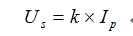
The principle of sampling resistance: S detection coil magnetic flux through the conversion flux detection module into a voltage signal, controls the power amplifier to increase or decrease the output, through the winding current increases or decreases, through continuous adjustment, eventually making the core B magnetic balance is achieved. The time of system balance is not more than 1 s. The current sample is sampled by the standard resistance R, and the Us is tested. The IP value can be calculated. At the same time, the magnetic flux signal can be used as a state signal such as alarm signal. In the form: K is a proportional constant.
The hardware and software design of the system of the sampling resistance system principle: the system is based on the current active principle is extended to design analog resistor, large current will be produced by the test input to the system current conversion module proportionally converted to small current, small voltage converted by a precision resistor, after sampling the voltage and gain proportional to the input voltage signal amplification module to the divider module, control the divider ratio by the controller, finally through the buffer circuit output voltage to the tested instrument sampling end to form a test loop. The resistance of the detection point resistance is adjusted by controlling the partial pressure ratio in the circuit of the voltage division module by the micro controller. Voltage sampling and program amplifying module output, the other voltage is input to the A/D sampling module, the controller calculates the corresponding current and makes correlation analysis. The schematic diagram is shown in Figure 3.
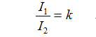
The system principle diagram, by the test instrument output current I1 through Broadband DC comparator to convert small current I2
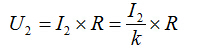
I1 - the large current produced by the test instrument. K Broadband DC comparator ratio. The small current I2 gets the voltage U2 after the precision resistance circuit.
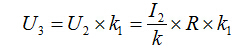
R - the resistance value of the precision resistance. Voltage U2 gets voltage U3 after voltage sampling and gain module
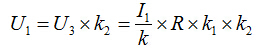
The ratio coefficient of voltage signal amplification by voltage sampling and program control amplifier module in K1 - U2. The voltage U3 is sent to the A/D sampling module, and the corresponding indication current is calculated by the controller and the correlation operation is analyzed. The output voltage value is U1 through the partial voltage module.
The proportionality coefficient of K2 - U3 is set by the controller by the voltage divider module. So the actual resistance value R1 measured by the resistance tester
采样电阻程序流程图


 铁芯B测量电路